Pneumatic systems are amongst the most common power transmission solutions to industrial automation. They utilize compressed air as the energy medium and provide a clean, safe, and cost-effective means of creating motion for manufacturing, packaging, material handling, and process control applications.
The components of a pneumatic system are important for engineers, manufacturers of OEM, maintenance teams, and system integrators in the design of reliable, efficient, and long-lasting automation equipment. This guide describes each major component, its function, and how all elements work together in a complete pneumatic system.
What Is a Pneumatic System?
A pneumatic system is one that changes the energy in compressed air into motion to accomplish a task like pushing, lifting, clamping, rotating, or placing machine parts.
In industrial automation, pneumatic systems are preferred for a number of important reasons:
- Simple System Structure
- Fast response and high cycle rates
- High reliability in harsh environments
- Intrinsic safety in explosive or flammable locations
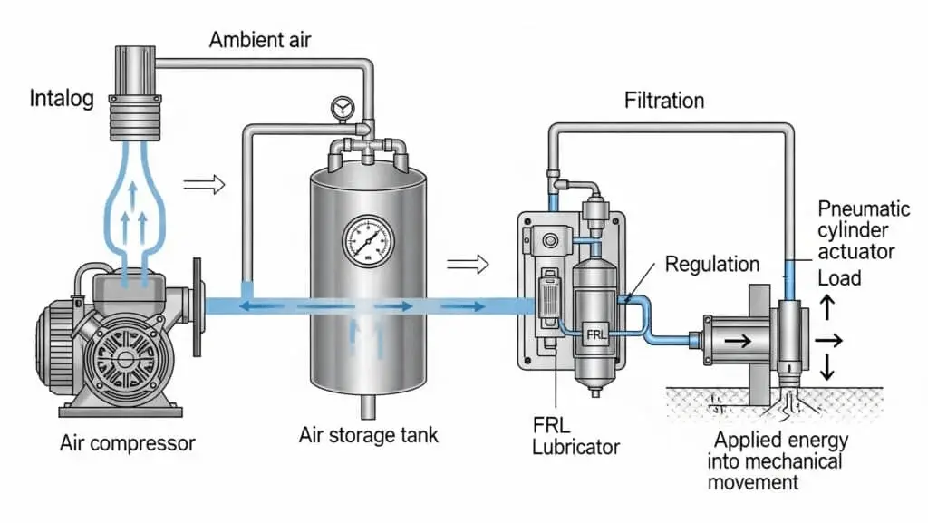
At a basic level, an individual pneumatic system consists of air generation, treatment, control, actuation, and distribution portions.
Main Components of a Pneumatic System

A standard pneumatic system can be divided into five functional sections:
- Air supply components
- Air preparation units
- Control components
- Actuators
- Air distribution and accessories
Each section plays a distinct and critical role in overall system performance.
1. Air Supply Components
Air Compressor
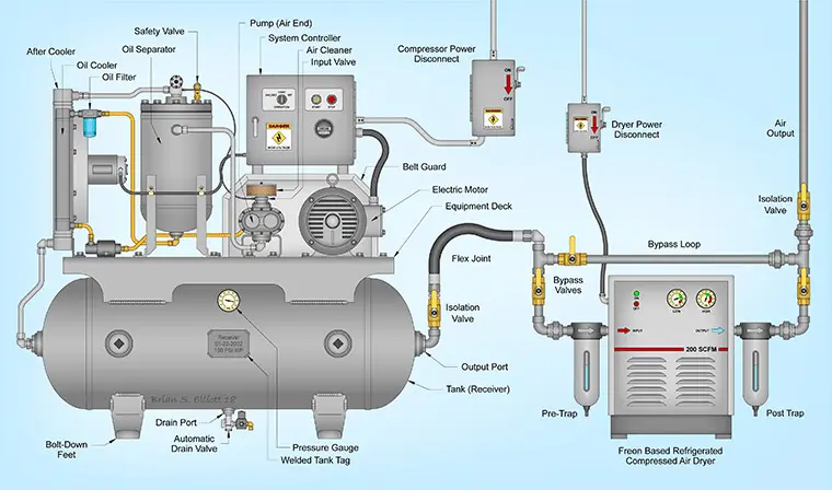
The air compressor is the heart of a pneumatic system. It draws in atmospheric air and compresses it to the pressure required by downstream components.
Common industrial compressor types include:
- Reciprocating compressors
- Rotary screw compressors
- Centrifugal compressors
For general industrial pneumatic applications, the typical operating pressure range is 5–8 bar (72–116 psi), depending on actuator force requirements, air consumption, and system design.
In real production environments, undersized compressors are one of the most common causes of unstable cylinder speed, pressure drops during peak load, and excessive energy consumption. A stable and adequately sized air supply is often the deciding factor for long-term system reliability.
Air Receiver (Air Tank)
The air receiver stores compressed air and serves multiple important functions:
- Stabilizing pressure fluctuations
- Reducing frequent compressor cycling
- Allowing moisture to condense and be drained
- Providing short-term peak airflow capacity
In medium to large pneumatic systems, properly sized air tanks significantly improve energy efficiency and extend compressor service life.
2. Air Preparation Components (FRL Units)
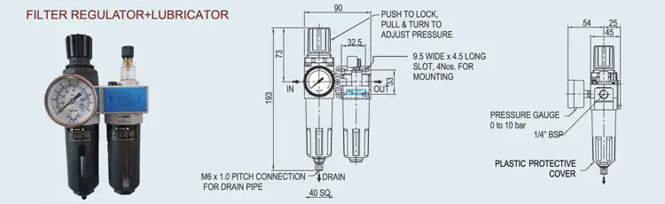
Compressed air leaving the compressor is not suitable for direct use. Before entering valves and actuators, it must be properly conditioned. This is the role of the FRL unit, which consists of a Filter, Regulator, and Lubricator.
Air Filter
The filter removes contaminants such as:
- Dust and solid particles
- Condensed water
- Oil aerosols from compression
Clean air prevents premature wear of seals, valve spools, and cylinder surfaces. In practice, inadequate filtration is a leading cause of early pneumatic component failure.
Pressure Regulator
The pressure regulator maintains a stable downstream pressure regardless of upstream fluctuations. Proper regulation ensures:
- Consistent actuator force and speed
- Improved motion repeatability
- Reduced air consumption and energy waste
Operating pneumatic systems at higher pressure than necessary is a common design mistake that increases leakage and shortens component lifespan.
Lubricator (Optional)
The lubricator introduces a controlled oil mist into the airflow to reduce friction and wear.
Many modern pneumatic components are designed for oil-free operation, and once lubrication is introduced, the entire system must remain lubricated. Lubricators are typically used in:
- High-speed or high-load cylinders
- Heavy-duty pneumatic tools
- Older systems designed for lubricated air
Correct selection is critical, as over-lubrication can be just as harmful as insufficient lubrication.
3. Control Components
Directional Control Valves
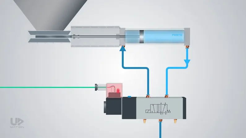
Directional control valves determine the path of airflow and control the movement direction of actuators.
Common valve configurations include:
- 2/2 valves
- 3/2 valves
- 5/2 valves
- 5/3 valves
They may be actuated by:
- Solenoids (electrical control)
- Pneumatic pilots
- Manual levers or mechanical cams
In automated systems, solenoid-operated valves are the most widely used due to easy PLC integration and fast response.
Flow Control Valves
Flow control valves regulate the airflow rate, directly controlling actuator speed. Typical applications include:
- Speed adjustment of pneumatic cylinders
- Smooth start and stop motion
- Preventing impact damage at end positions
In many real-world systems, improper flow control settings are responsible for vibration, noise, and reduced mechanical accuracy.
Pressure Control Valves
Pressure control devices include:
- Pressure relief valves
- Pressure reducing valves
- Safety valves
These components protect the system from overpressure conditions and help ensure safe operation in accordance with industrial safety standards.
4. Actuators
Actuators convert compressed air energy into mechanical movement.
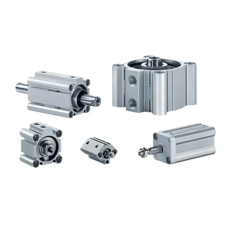
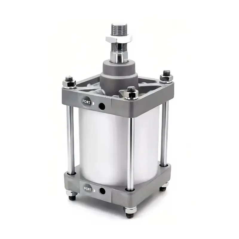
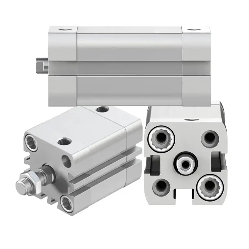
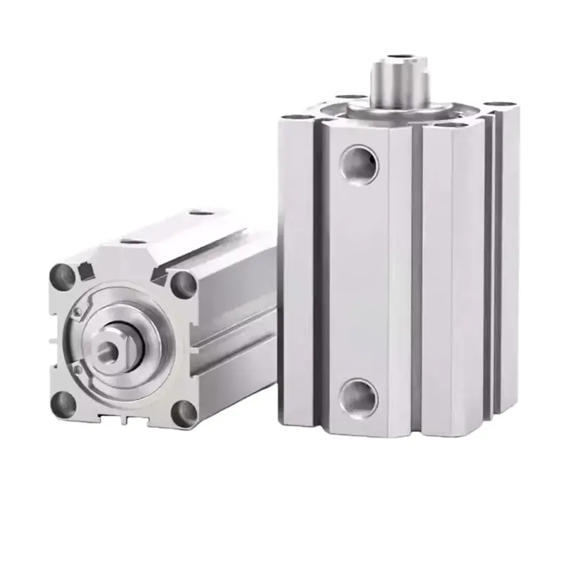
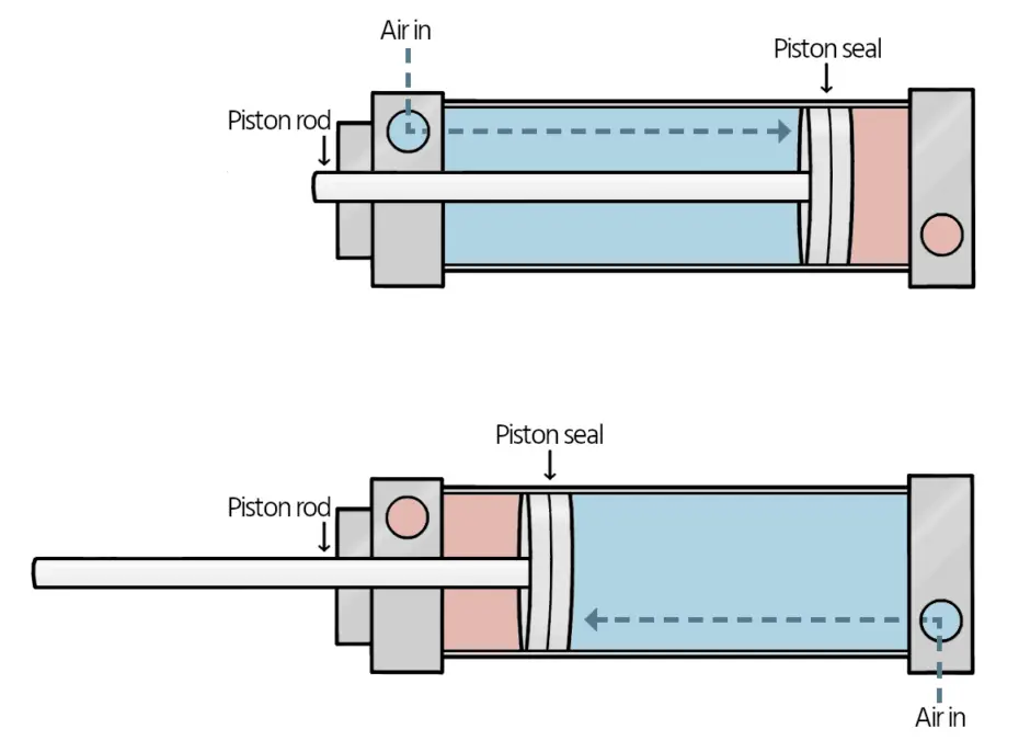
Pneumatic Cylinders
Pneumatic cylinders are the most commonly used actuators, providing linear motion for industrial applications such as pushing, lifting, clamping, and positioning.
Common types include:
- Single-acting cylinders
- Double-acting cylinders
- Compact cylinders
- Rodless cylinders
Double-acting cylinders are widely used due to their controllable motion, reliability, and suitability for continuous operation.
Rotary Actuators
Rotary actuators generate angular motion and are commonly used for:
- Valve actuation
- Indexing tables
- Pick-and-place mechanisms
Typical designs include rack-and-pinion and vane-type rotary actuators, offering rotation angles from 90° up to 360°. Pneumatic rotary actuators are especially suitable for fast, repetitive motion with moderate torque requirements.
5. Air Distribution and Accessories
Air distribution components connect the entire system and are often underestimated in importance.
Key accessories include:
- Pneumatic tubing and hoses
- Push-in fittings and couplings
- Manifolds
- Silencers (mufflers)
In many factories, air leakage at fittings and joints is the largest hidden source of compressed air energy loss. Poor-quality fittings or undersized tubing can cause pressure drops, unstable actuator motion, and reduced system efficiency.
How Pneumatic System Components Work Together
A complete pneumatic system follows a logical flow:
- Air is compressed by the air compressor
- Compressed air is stored and stabilized in the air receiver
- Air is cleaned and regulated by the FRL unit
- Valves control airflow direction, pressure, and speed
- Actuators convert air energy into mechanical motion
Each component directly affects overall system performance. Studies show that air leakage, improper air preparation, and excessive pressure settings can waste up to 30% of compressed air energy in poorly designed systems.
Common Pneumatic System Design Mistakes
Even with high-quality components, performance issues can occur due to system design errors, such as:
- Undersized air compressors
- Inadequate air filtration
- Excessively high operating pressure
- Ignoring air leakage during maintenance
- Poor compatibility between components
Addressing these issues early in the design stage can significantly improve efficiency and reduce lifecycle costs.
Pneumatic vs. Hydraulic vs. Electric Systems
| Feature | Pneumatic | Hydraulic | Electric |
|---|---|---|---|
| Medium | Air | Oil | Electricity |
| Cleanliness | Very clean | Risk of oil leaks | Clean |
| Force output | Medium | Very high | Medium |
| System cost | Low–medium | High | Medium–high |
| Safety | High | Medium | Medium |
These characteristics make pneumatic systems especially suitable for food processing, packaging, electronics assembly, and general industrial automation.
Selection Tips for Pneumatic System Components
When selecting pneumatic components, consider:
- Required operating pressure and airflow
- Environmental conditions (dust, moisture, temperature)
- Duty cycle and speed requirements
- Long-term maintenance and energy efficiency
For OEM manufacturers and system integrators, working with experienced pneumatic component suppliers that offer application guidance and sizing support can reduce design risk and improve system reliability.
FAQ
1. What are the basic components of a pneumatic system?
A basic pneumatic system includes an air compressor, air receiver, FRL unit, control valves, actuators, and air distribution accessories.
2. Is an FRL unit always necessary?
In most industrial applications, yes. Proper air filtration and pressure regulation significantly extend component lifespan and improve system reliability.
3. What is the most commonly used pneumatic actuator?
The double-acting pneumatic cylinder is the most widely used due to its simplicity, reliability, and controllable motion.
4. Can pneumatic systems operate without lubrication?
Many modern pneumatic components are designed for oil-free operation, depending on seal materials and operating conditions.
5. How often should pneumatic components be maintained?
Routine inspection of filters, valves, fittings, and air leakage is typically recommended every 3–6 months in continuous-operation systems.
Conclusion
A pneumatic system is only as reliable as its individual components and overall design. By understanding the function and interaction of air supply equipment, air preparation units, valves, actuators, and accessories, engineers can build systems that are efficient, durable, and cost-effective.
For automation equipment manufacturers and system integrators, selecting high-quality pneumatic components supported by solid engineering expertise is a key factor in achieving stable long-term performance.