A Practical Guide to Pneumatic Control Valves in Automation Systems
Control valves are a vital component in the world of modern pneumatic control systems. By using control valves, air flow is directed, pressurized, and distributed in the desired direction. Various machines, including assembly lines, robots, as well as packaging equipment, are capable of functioning because of these control valves that distribute air in the right way at the right time.
In this guide, we are going to explain how a pneumatic control valve works, break down its operating principle, identify some of its common types, and address selection tips based on its usage in industry.
What Is a Control Valve in a Pneumatic System?
In pneumatic applications, a control valve—often referred to as an air control valve—is a mechanical or electromechanical device used to manage compressed air within a system.
Its primary functions include:
- Directing airflow to different ports
- Regulating air pressure
- Controlling airflow rate
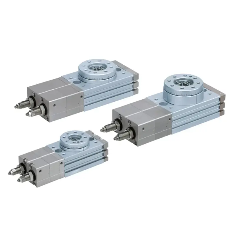
In practice, pneumatic control valves act as the system’s decision-making components, responding to electrical signals, pilot air, or manual input to control actuators such as air cylinders and rotary actuators.
Unlike process control valves used in liquid or gas regulation, pneumatic control valves focus on fast switching, repeatable motion, and reliable air control in automation environments.
Core Working Principle of a Pneumatic Control Valve
At its most basic level, a pneumatic control valve works by opening, closing, or partially blocking internal air passages to guide compressed air through the system.
From an engineer’s perspective, this is how the system decides:
- Which actuator moves
- In which direction it moves
- How fast and how smoothly it operates
Key Operating Steps
- Input Signal Received
The valve receives a control signal, which may be:- Electrical (solenoid signal)
- Pneumatic (pilot air)
- Mechanical (manual lever or cam)
- Actuation Mechanism Engaged
The signal activates an internal actuator such as a solenoid coil, diaphragm, or piston. - Valve Element Moves
Internal components—such as a spool, poppet, or disc—shift position. - Airflow Path Changes
The movement redirects compressed air, altering:- Flow direction
- Flow rate
- System pressure
- Actuator Responds
Air cylinders or pneumatic tools perform the required mechanical motion.
Main Types of Pneumatic Control Valves
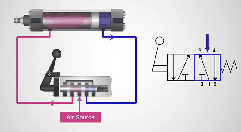
1. Directional Control Valves
Directional control valves determine where the air goes, controlling whether an actuator extends, retracts, or stops.
Common configurations include:
- 2/2-way valves
- 3/2-way valves
- 5/2-way valves
- 5/3-way valves
These valves are widely used with single-acting and double-acting air cylinders and form the backbone of most pneumatic automation systems.
2. Flow Control Valves
Flow control valves regulate the speed of airflow, directly affecting how fast an actuator moves.
Typical functions include:
- Meter-in control
- Meter-out control
- Bi-directional flow regulation
In real-world applications, improper flow control often leads to jerky motion, excessive noise, or premature mechanical wear, especially in high-speed automation lines.
3. Pressure Control Valves
Pressure control valves maintain system stability and safety by managing air pressure levels.
Common types include:
- Pressure regulators
- Pressure relief valves
- Pressure reducing valves
Proper pressure regulation improves energy efficiency, protects downstream components, and extends overall system lifespan.
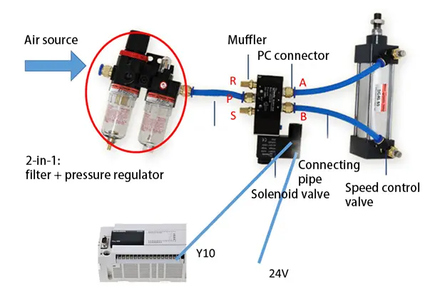
4. Solenoid-Operated Pneumatic Control Valves
Solenoid valves use an electromagnetic coil to actuate the valve mechanism.
Key advantages include:
- Fast response time
- Easy integration with PLC control systems
- High repeatability and automation compatibility
Technically, solenoid valves are not a separate functional category, but rather an actuation method commonly applied to directional, flow, or pressure control valves.
Solenoid air control valves are the most widely used option in modern automated pneumatic systems.
Applications of Pneumatic Control Valves
Pneumatic control valves are used across a wide range of industries, including:
- Industrial automation and assembly lines
- Packaging and bottling machinery
- Robotics and material handling systems
- Automotive manufacturing
- Food and beverage processing equipment
- Medical and laboratory devices
In each application, air control valves ensure accurate timing, repeatable motion, and safe operation.
Market Trends in Pneumatic Control Systems
With the growth of Industry 4.0 and smart manufacturing, pneumatic control valves are evolving toward:
- Energy-efficient valve designs
- Compact, modular valve manifolds
- Integration with digital sensors
- Predictive maintenance and condition monitoring
Despite increased electrification, pneumatic systems remain competitive due to:
- Lower system cost compared to fully electric solutions
- High reliability in harsh or contaminated environments
- Simple installation and maintenance
Key Technical Parameters to Consider
When selecting a pneumatic control valve, engineers typically evaluate the following parameters:
| Parameter | Description |
|---|---|
| Operating Pressure | Minimum and maximum air pressure |
| Port Size | Common sizes: G1/8, G1/4, G3/8, G1/2 |
| Flow Rate (Cv) | Determines air delivery capacity |
| Actuation Type | Solenoid, pneumatic pilot, manual |
| Voltage | 12V DC, 24V DC, 110V AC, 220V AC |
| Response Time | Speed of valve switching |
Correct parameter matching helps improve efficiency, reduce air consumption, and extend component life.
Control Valves vs Other Pneumatic Components
Compared with other pneumatic components such as:
- FRL units (air preparation)
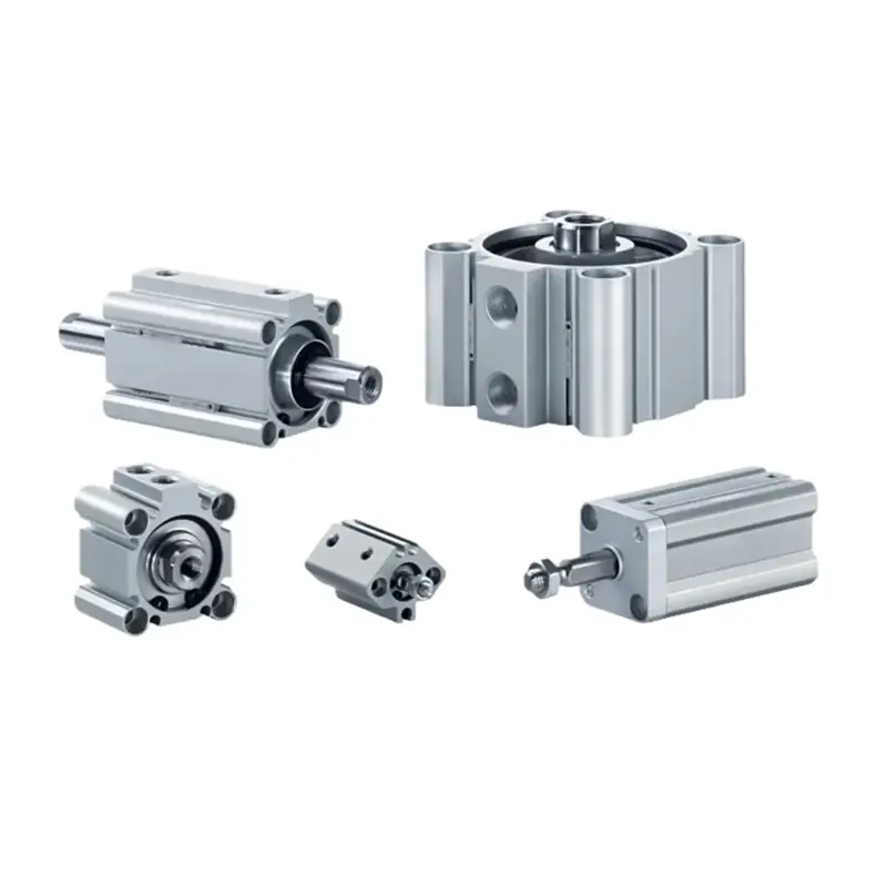
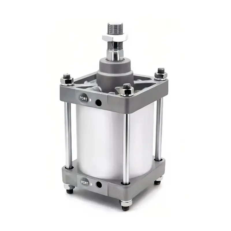
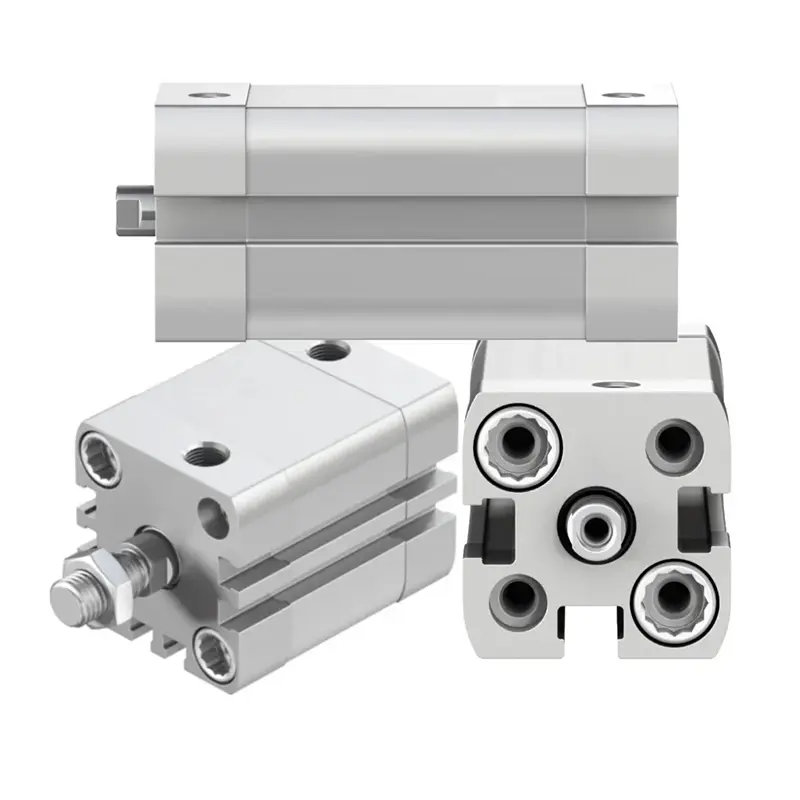
- Air cylinders (actuation)
- Fittings and tubing (air delivery)
Control valves are unique because they actively manage system logic and behavior, not just airflow.
Without properly selected control valves, even high-quality pneumatic components cannot perform reliably.
Common Selection Mistakes in Pneumatic Control Valves
In practical applications, system performance issues often result from incorrect valve selection rather than valve failure itself. Common mistakes include:
- Undersized valves causing slow or unstable cylinder motion
- Incorrect solenoid voltage selection
- Ignoring air quality and filtration requirements
- Using low-cost valves in high-cycle or continuous-duty applications
Avoiding these issues significantly improves system reliability and reduces long-term maintenance costs.
How to Choose the Right Air Control Valve
When selecting a pneumatic control valve, consider:
- Type of actuator (single-acting or double-acting)
- Required airflow capacity
- Control method (PLC, manual, pilot air)
- Installation space and manifold compatibility
- Environmental conditions (dust, moisture, temperature)
For OEMs and system integrators, working with an experienced pneumatic control valve manufacturer helps ensure correct selection and long-term system stability.
Why Quality Matters in Pneumatic Control Valves
Low-quality control valves often lead to:
- Internal air leakage
- Inconsistent actuation
- Premature seal and spool wear
- Increased downtime and maintenance costs
In many systems, performance degradation is caused not by cylinders or compressors, but by unstable or leaking control valves that gradually affect system behavior.
Reliable valve design and manufacturing quality are key contributors to overall system efficiency and uptime.