Engineering Principles, NFPA/ISO Standards, Side Load Prevention & Best Practices
Pneumatic cylinders—also known as air cylinders—are essential actuators in industrial automation. From packaging machinery and automotive production lines to electronics assembly and material handling systems, they convert compressed air energy into precise linear motion.
However, improper pneumatic cylinder installation remains one of the most common causes of actuator failure. Misalignment, incorrect mounting selection, poor air quality, or side loading can dramatically shorten service life and reduce system efficiency.
This ultimate guide explains:
- How pneumatic cylinders work
- How to install a pneumatic cylinder correctly
- All major mounting types
- NFPA and ISO mounting codes
- Side load engineering principles
- Alignment and tolerance best practices
- Real-world installation scenarios
- Common mistakes to avoid
Whether you are an OEM engineer, maintenance technician, or automation designer, this guide provides the technical depth needed for reliable cylinder performance.
Executive Summary: Key Installation Principles
If you need a quick reference, remember these five rules:
- Always align the piston rod with the load centerline.
- Prevent radial side load at all costs.
- Select mounting type based on force direction and motion path.
- Ensure compressed air meets ISO 8573-1 purity class requirements.
- Never use a standard pneumatic cylinder as a structural guide.
Installation quality directly determines cylinder lifespan, maintenance frequency, and system stability.
1. How a Pneumatic Cylinder Works
A pneumatic cylinder generates force according to:
F = P × A
Where:
- F = Force (N)
- P = Operating pressure (Pa)
- A = Effective piston area (m²)
Example Calculation
Operating pressure: 0.6 MPa
Bore diameter: 50 mm
Radius = 25 mm = 0.025 m
Area:
A = π × (0.025)² ≈ 0.00196 m²
Force:
F = 0.6 × 10⁶ × 0.00196 ≈ 1176 N
Actual usable force should account for approximately 10–15% friction loss.
This calculation is essential when selecting and installing a pneumatic cylinder to ensure adequate thrust capacity.
2. Complete Pneumatic Cylinder Installation Checklist
Pre-Installation
- Verify bore size and stroke length
- Confirm operating pressure range
- Identify correct mounting type
- Check port thread compatibility
- Confirm magnetic piston (if sensor required)
Mechanical Mounting
- Align rod axis with load axis
- Avoid offset thrust line
- Use correct mounting brackets
- Apply recommended bolt torque
Air Connection
- Use flexible tubing
- Avoid sharp bends
- Ensure ports are stress-free
- Install FRL unit (Filter-Regulator-Lubricator)
Cushion Adjustment
- Start fully open
- Gradually tighten
- Achieve smooth deceleration
- Avoid over-restriction
Commissioning
- Test at 30–50% operating pressure
- Check for leakage and abnormal noise
- Cycle repeatedly before full load operation
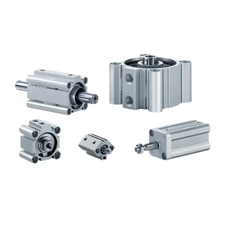
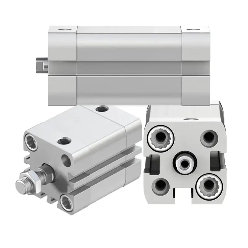
3. Pneumatic Cylinder Mounting Types Explained
Selecting the proper mounting configuration is critical for reliability.
3.1 Fixed Centerline Mountings
Best for straight-line force applications.
- High rigidity
- Suitable for push or pull loads
- Sensitive to misalignment
Flange Mount (Front/Rear)
Centerline Lug Mount
- Tabs located at head and cap
- Suitable for straight force transfer
- Dowel pins recommended in high-shock environments
Extended Tie Rod Mount
- Tie rods extend beyond cylinder body
- Conforms to many NFPA standards
- Good axial load transmission
Fixed centerline mountings must be attached to rigid machine frames to prevent deflection.
3.2 Fixed Non-Centerline Mountings
The thrust line is parallel to but offset from the rod axis.
Side Mount
- Easy installation
- Produces bending moment
- Mounting surface must resist torque
Foot Mount
- Front or rear foot attachment
- May introduce shear stress in large-bore cylinders
Offset thrust lines create additional bending forces and must be carefully engineered.
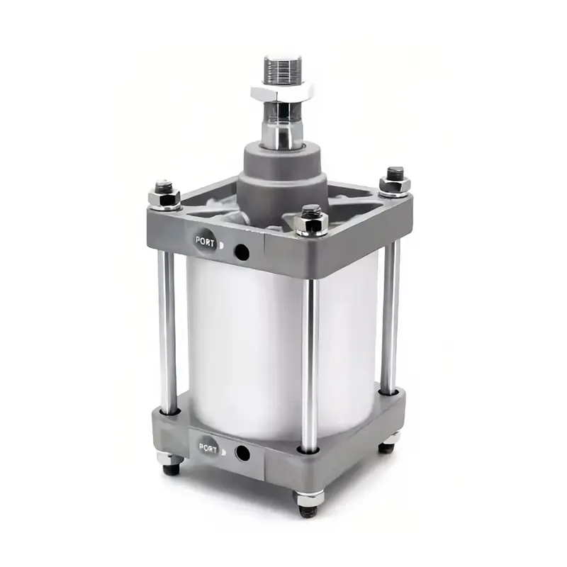
3.3 Pivoted Centerline Mountings
Ideal for curved or angular motion.
Clevis Mount
- Allows angular compensation
- Economical
- Suitable for short strokes
Trunnion Mount
- Allows rotational movement
- Suitable for long stroke cylinders
- Must resist shear rather than bending stress
Intermediate trunnion mounts should be placed near the balance point of long cylinders to reduce stress.
4. NFPA & ISO Mounting Codes Explained
Understanding cylinder mounting codes simplifies selection and compatibility.
4.1 NFPA Mounting Code System
NFPA codification uses letters and numbers:
First letter:
M = Mount
A = Accessory
Second letter:
B – Body
E – Head/Cap
F – Flange
P – Pivot
R – Threaded Nose
S – Foot/Lugs
T – Trunnion
X – Studs/Tie Rods
Number: Version or configuration variation
Example:
MF1 – Front flange mount
MF2 – Rear flange mount
MDF1 – Double rod front flange mount
4.2 ISO Standards
Common standards include:
- ISO 15552 (profile cylinders)
- ISO 6431
- ISO 21287 (compact cylinders)
These standards ensure dimensional interchangeability between manufacturers.
For OEM projects, selecting ISO-compliant cylinders simplifies global sourcing and maintenance.
5. Side Load Engineering: The Leading Cause of Failure
What Is Side Load?
Side load refers to radial force acting perpendicular to the piston rod axis.
It may result from:
- Misalignment
- Overhung load
- Inertia forces
- Offset mounting
Why Side Load Is Dangerous
Side load creates bending moment:
Moment = Force × Distance
Consequences include:
- Uneven seal wear
- Increased friction
- Rod bending
- Bearing scoring
- Reduced lifespan
How to Prevent Side Load
- Use external linear guides
- Install slide tables
- Support load independently
- Use guided cylinders when necessary
- Add floating joints for minor misalignment
A standard pneumatic cylinder should never act as a structural guide.
6. Alignment & Tolerance Considerations
Three types of misalignment:
- Angular misalignment
- Parallel misalignment
- Axial misalignment
Misalignment increases internal friction and accelerates wear.
Best practice:
Minimize deviation within manufacturer-recommended tolerance values and use flexible couplings when required.
7. Installation by Application Scenario
Vertical Installation
- Compensate for gravity load
- Ensure sufficient upward thrust
- Consider safety locking mechanism
Long Stroke Cylinders
- Risk of rod sagging
- Consider intermediate trunnion
- Evaluate column strength
High-Speed Automation
- Fine-tune cushioning
- Use shock absorbers if required
- Maintain stable air supply
Heavy Load Systems
- Reinforced mounting brackets
- Higher bearing capacity
- Guided cylinder preferred
8. Standard vs Guided Pneumatic Cylinder
| Feature | Standard Cylinder | Guided Cylinder |
|---|---|---|
| Side Load Resistance | Low | High |
| Precision | Moderate | High |
| Installation Sensitivity | High | Moderate |
| Cost | Lower | Higher |
| Service Life (under side load) | Reduced | Extended |
For applications involving off-center load, long stroke, or precision motion, guided cylinders significantly improve durability.
CHDAC provides both ISO-standard and reinforced guided pneumatic cylinders for high-cycle industrial automation systems.
9. Common Installation Mistakes
Avoid these critical errors:
- Ignoring alignment tolerance
- Using piston rod as structural support
- Over-tightening mounting bolts
- Installing without air filtration
- Incorrect cushioning adjustment
- Allowing unsupported load
- Ignoring operating pressure limits
Correct installation can extend cylinder service life significantly.
10. Environmental & Mechanical Factors Affecting Mounting
Consider:
- Corrosive atmosphere
- Temperature range
- Vibration level
- Space constraints
- Operating pressure
- Mount material strength
Proper material selection and stress analysis improve long-term stability.
11. Maintenance & Inspection After Installation
- Inspect mounting bolts every 3–6 months
- Monitor air quality
- Check for abnormal noise
- Verify smooth motion
- Re-adjust cushioning if necessary
Preventive maintenance reduces unexpected downtime.
FAQ
Yes. Ensure sufficient force to overcome gravity and consider safety locking for vertical loads.
The first letter indicates mount type (M), the second letter indicates style (F = flange, T = trunnion, etc.), and numbers represent configuration versions.
Side load increases friction, causes rod bending, and shortens seal life.
Many modern cylinders use pre-lubricated seals. If lubrication is used, it must be continuous.
Misalignment should remain within manufacturer-specified tolerances. Floating joints may help compensate minor deviation.
Conclusion
Pneumatic cylinder installation is not merely mechanical assembly—it is a precision engineering process that determines performance, durability, and lifecycle cost.
By ensuring:
- Proper mounting selection
- Accurate alignment
- ISO-compliant air quality
- Side load prevention
- Correct cushioning adjustment
You maximize system reliability and reduce downtime risk.
Need Engineering Support for Pneumatic Cylinder Selection?
Selecting and installing the correct pneumatic cylinder is critical for automation success.
CHDAC supports OEMs and automation manufacturers with:
- Load force calculation assistance
- ISO-standard and customized cylinder production
- Guided cylinder solutions
- High-cycle durability design
- Technical consultation for mounting optimization
Contact our engineering team for application-specific recommendations and project evaluation.