Pneumatic control systems are commonly used in industrial automation control systems, packaging machines, automotive assembly lines, and manufacturing equipment.
The question is: But how exactly does a user control a pneumatic device like a pneumatic cylinder or pneumatic actuator?
This guide covers the following topics: the basics of pneumatics control, comparison of manual and automated control, and selection tips for engineers and OEM buyers.
1. What Does It Mean to Control a Pneumatic Device?
A pneumatic device converts compressed air energy into linear or rotary motion.
The user does not directly move the actuator. Instead, they control:
- Airflow direction
- Operating pressure
- Flow rate (speed)
- Motion sequence and timing
When compressed air is routed into an actuator chamber, it generates force based on:
Force = Pressure × Effective Area
This is why pressure stability and valve control are critical in pneumatic systems.
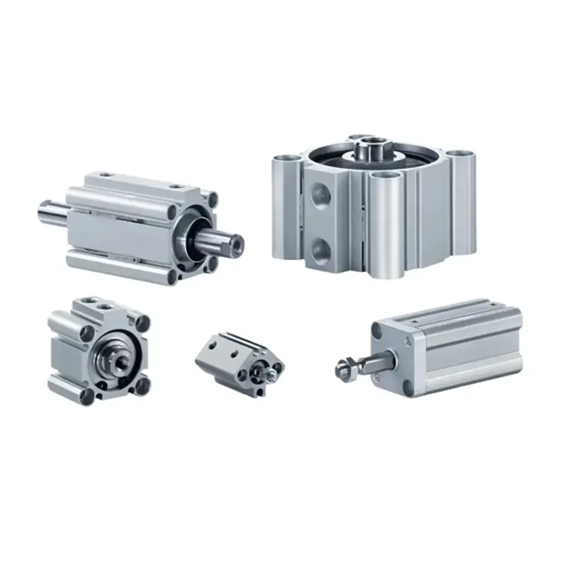
Typical controlled devices include:
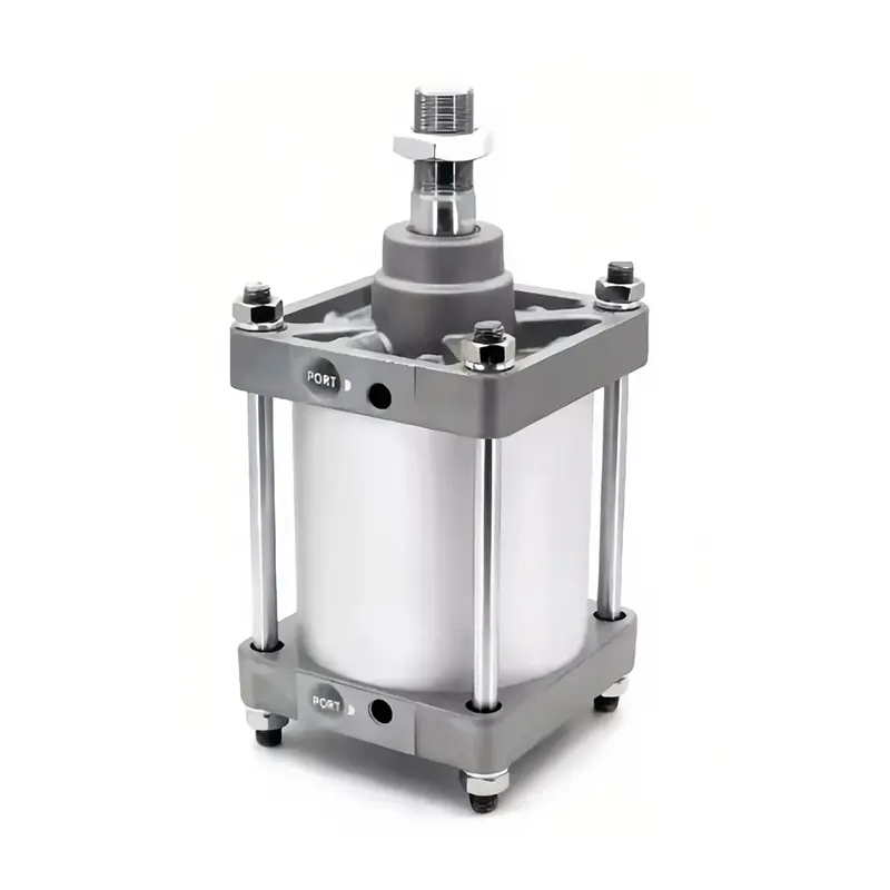
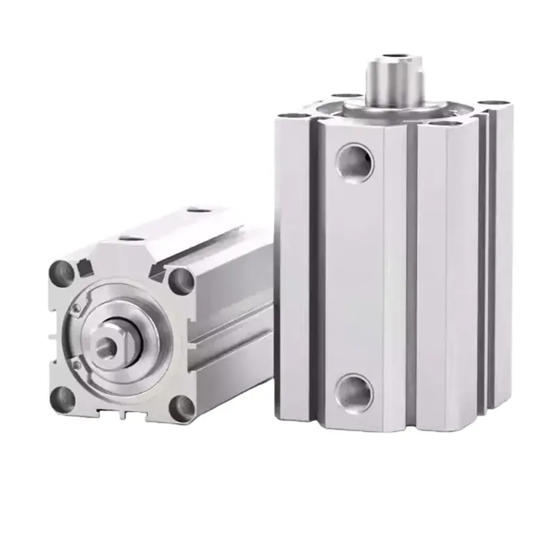
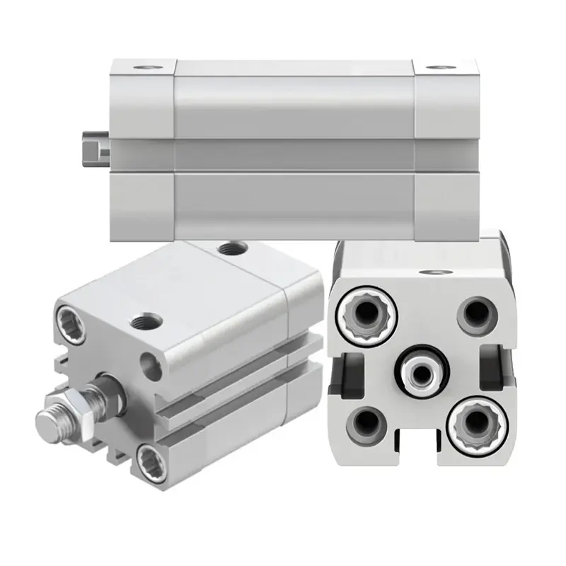
- Single-acting cylinders
- Double-acting cylinders
- Pneumatic grippers
- Rotary actuators
- Air motors
The control system determines when and how compressed air reaches these actuators.
2. Main Pneumatic Control Methods
Different applications require different control strategies. Below are the most common pneumatic control methods used in industry.
2.1 Manual Pneumatic Control
Manual control uses mechanically actuated valves.
Common devices include:
- Push-button valves
- Hand lever valves
- Foot pedal valves
- Toggle valves
When the operator actuates the valve, airflow direction changes immediately, causing the cylinder to extend or retract.
Where Manual Control Is Used
Manual pneumatic control remains common in:
- Workbench fixtures
- Clamping stations
- Semi-automatic equipment
- Maintenance operations
It is cost-effective and reliable. However, it is not suitable for high-speed production or synchronized multi-cylinder systems.
2.2 Solenoid Valve Control (Electro-Pneumatic Control)
In modern factories, pneumatic devices are usually controlled electrically via solenoid valves.
How Solenoid Valve Control Works
- Operator presses a button or PLC sends a signal
- Solenoid coil energizes
- Valve spool shifts
- Compressed air is redirected
- Cylinder moves
This method allows:
- Remote operation
- PLC integration
- High repeatability
- Automated timing control
Electro-pneumatic systems are now standard in packaging lines, CNC auxiliary systems, and automated assembly equipment.
For example, a 5/2 solenoid valve is typically used to control a double-acting pneumatic cylinder in automation systems.
2.3 PLC-Controlled Pneumatic Systems
In advanced manufacturing environments, pneumatic devices are controlled by PLCs or industrial control systems.
The user interacts with:
- HMI (Human Machine Interface)
- Control panel
- SCADA system
The PLC manages logic sequences such as:
- Cylinder A extends
- Sensor confirms position
- Cylinder B retracts
- Timer initiates next cycle
This approach enables:
- High-speed automation
- Multi-actuator synchronization
- Reduced human error
- Precise production sequencing
PLC-based pneumatic control is widely used in automotive production and automated packaging lines.
3. Key Components in a Pneumatic Control System
To understand how a user controls a pneumatic device, it’s important to look at the full control chain.
3.1 Air Preparation Unit (FRL)
An FRL unit includes:
- Filter
- Regulator
- Lubricator
Proper air preparation ensures:
- Stable pressure
- Clean airflow
- Reduced valve sticking
- Longer seal life
Contaminated air can cause unstable cylinder speed, internal leakage, and premature component failure.
For industrial systems, stable pressure regulation is essential for consistent actuator force.
3.2 Directional Control Valves
Directional control valves determine airflow path.
Common types include:
- 3/2 valve (single-acting cylinder)
- 5/2 valve (double-acting cylinder)
- 5/3 valve (mid-position control)
Valve selection directly affects:
- Motion control
- Safety
- System flexibility
For automated systems, solenoid-operated directional valves are most commonly used.
3.3 Flow Control Valves
Flow control valves regulate actuator speed by adjusting airflow.
Without proper flow control:
- Cylinders may move too fast
- Mechanical shock may occur
- Position accuracy decreases
Speed control is usually achieved by throttling exhaust air for better stability.
3.4 Sensors and Feedback Devices
Modern pneumatic control systems often include:
- Reed switches
- Proximity sensors
- Pressure switches
These components provide position and pressure feedback to the PLC, improving system reliability and repeatability.
4. Pneumatic Control vs Other Actuation Technologies
Pneumatic vs Hydraulic
Pneumatic systems:
- Faster response
- Cleaner operation
- Lower force density
Hydraulic systems:
- Higher force output
- Better for heavy-load applications
- More complex maintenance
Pneumatic vs Electric Actuators
Pneumatic actuators:
- Cost-effective
- Ideal for repetitive motion
- Suitable for harsh environments
Electric actuators:
- Precise positioning
- Programmable control
- Higher initial investment
Selection depends on force requirements, positioning accuracy, and cost considerations.
5. Common Pneumatic Control Problems (And Causes)
This section helps capture long-tail search traffic and provides real engineering value.
1. Pneumatic cylinder not moving
Possible causes:
- No air supply
- Solenoid coil failure
- Valve spool stuck
- Insufficient pressure
2. Cylinder speed too slow
Possible reasons:
- Flow control over-restricted
- Air leakage
- Pressure drop
- Undersized valve
3. Inconsistent cylinder force
Likely due to:
- Unstable regulator
- Contaminated air
- Internal seal wear
Stable air preparation and correct valve sizing are critical for reliable operation.
6. How to Choose the Right Pneumatic Control Method
When selecting a pneumatic control solution, engineers should consider:
1. Required Automation Level
- Manual operation
- Semi-automatic
- Fully PLC controlled
2. Operating Environment
- High temperature
- Dust or moisture
- Hazardous area
3. Load and Force Requirements
Cylinder bore size and operating pressure determine output force.
4. Speed and Cycle Time
High-speed systems require properly sized valves and minimal pressure drop.
5. Maintenance Capability
More complex control systems require trained technicians.
For OEM equipment manufacturers, selecting the correct pneumatic control architecture improves long-term reliability and reduces downtime.
7. Engineering Perspective: Typical Electro-Pneumatic Architecture
A typical industrial pneumatic control system includes:
- Air compressor
- FRL unit
- 5/2 solenoid valve
- Flow control valves
- Double-acting cylinder
- Position sensors
- PLC controller
- HMI interface
The user interacts only with the HMI or control panel, while the system manages airflow automatically.
8. Why Pneumatic Control Remains Popular in Industry
Despite advances in electric actuation, pneumatic systems remain widely adopted because they offer:
- Simple structure
- Fast actuation speed
- Lower system cost
- Safe operation in explosive environments
- Easy maintenance
For small and medium-sized automation equipment, pneumatic control often provides the best balance between performance and cost.
9. Conclusion
Controlling a pneumatic device means managing air direction, pressure, flow, and timing through manual valves, solenoid valves, or PLC-based systems.
From simple push-button control to fully automated electro-pneumatic integration, the right method depends on application complexity, budget, and production goals.
Understanding pneumatic control principles is essential for building stable, efficient, and safe automation systems.
About CHDAC Pneumatic Solutions
As a manufacturer of pneumatic cylinders, air preparation units, and solenoid valves, CHDAC provides complete pneumatic control solutions for industrial automation.
If you are designing new equipment or upgrading an existing pneumatic control system, our engineering team can assist with:
- Valve selection
- Cylinder sizing
- Air preparation configuration
- OEM customization
Contact us to discuss your application requirements.