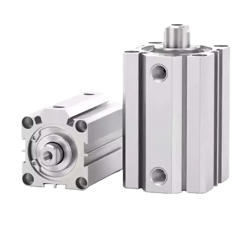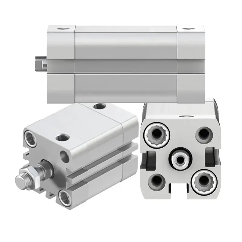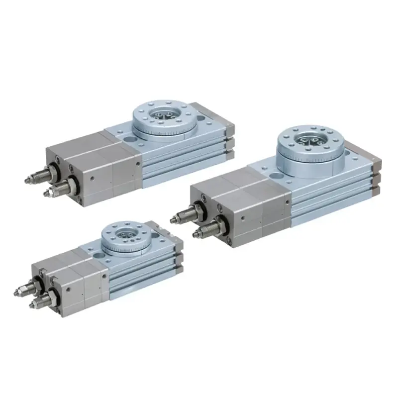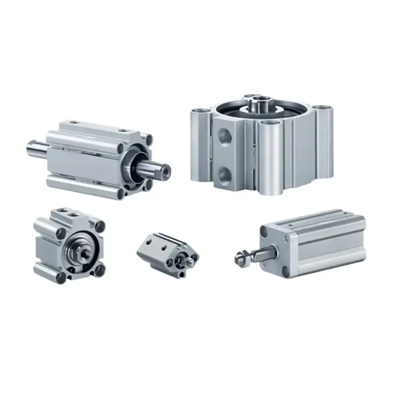
Pneumatic actuators are devices that convert compressed air energy into mechanical motion. The main types include linear pneumatic cylinders, rotary actuators, and pneumatic grippers, each designed for different motion and automation requirements.
In industrial automation, choosing the right pneumatic actuator depends on several factors, including the required motion, force or torque, stroke or rotation angle, operating speed, installation space, environment, and expected service life.
As a professional pneumatic actuator manufacturer, CHDAC provides a range of pneumatic cylinders and rotary actuator solutions for industrial automation, machinery, material handling, packaging, and OEM applications.
What Is a Pneumatic Actuator?
A pneumatic actuator is a mechanical device that converts the energy of compressed air into controlled mechanical movement.
Depending on the actuator design, the output motion can be:
- Linear motion – straight-line movement
- Rotary motion – angular or rotational movement
- Gripping motion – opening and closing of gripping jaws
Pneumatic actuators are widely used in industrial automation because they offer a relatively simple mechanical design, fast response, easy installation, and reliable operation in repetitive motion applications.
A typical pneumatic system includes:
Air compressor → Air treatment → Control valve → Pneumatic actuator → Mechanical load
Air treatment components such as filters, regulators, and lubricators may be used to improve air quality and regulate operating pressure. The control valve determines when and where compressed air enters the actuator.
Key Advantages of Pneumatic Actuators
Pneumatic actuators are commonly selected for applications requiring:
- Fast repetitive movement
- Simple mechanical construction
- Reliable operation
- Low initial equipment cost
- Easy replacement and maintenance
- High power-to-size ratio
- Clean operation when properly designed and supplied with suitable compressed air
- Safe operation in applications where electrical actuation may be undesirable
However, pneumatic systems also have limitations. Compressed-air generation can be energy-intensive, and air leakage, poor pressure regulation, or inadequate air treatment can reduce overall system efficiency.
How Do Pneumatic Actuators Work?
The working principle of a pneumatic actuator is based on the controlled application of compressed air pressure.
In a typical pneumatic cylinder, compressed air enters one side of a cylinder chamber and acts on the piston. The resulting pressure force moves the piston rod.
For a basic pneumatic cylinder, the theoretical force can be estimated using:
F = P × A
Where:
- F = theoretical force
- P = working pressure
- A = effective piston area
For a cylinder extending under pressure, the piston area is approximately:
A = πD² / 4
Where D is the piston diameter.
In a double-acting cylinder, compressed air can be supplied to either side of the piston to produce movement in both directions.
The actual output force is lower than the theoretical value because of factors such as:
- Seal friction
- Mechanical resistance
- Pressure losses
- Airflow restrictions
- Cushioning effects
- Load conditions
Therefore, engineers should consider an appropriate safety factor when sizing a pneumatic actuator.
Main Types of Pneumatic Actuators
Pneumatic actuators can be classified according to the type of motion they produce and their internal operating mechanism.
The most common categories are:
- Linear pneumatic actuators
- Rotary pneumatic actuators
- Pneumatic grippers
- Diaphragm-type pneumatic actuators
Let’s examine each type in detail.
1. Linear Pneumatic Actuators: Air Cylinders
Linear pneumatic actuators, commonly called pneumatic cylinders or air cylinders, generate straight-line movement.
They are among the most widely used pneumatic actuators in industrial automation.
A typical pneumatic cylinder consists of:
- Cylinder tube
- Piston
- Piston rod
- Seals
- End covers
- Cushioning components, depending on the design
- Mounting components
Pneumatic cylinders are available in many configurations to meet different load, space, speed, and mounting requirements.
1.1 Single-Acting Pneumatic Cylinders
A single-acting pneumatic cylinder uses compressed air to move the piston in one direction. A spring returns the piston to its original position when air pressure is released.
How Single-Acting Cylinders Work
Compressed air is supplied to one side of the piston. When the air pressure is sufficient to overcome the spring force and external load, the piston moves.
When the air supply is removed, the spring returns the piston.
Advantages
- Simple construction
- Lower air consumption in some applications
- Easy control
- Suitable for short-stroke operations
Typical Applications
Single-acting cylinders are commonly used for:
- Clamping
- Ejecting
- Stopping
- Simple positioning
- Light-duty pressing
- Part release mechanisms
A single-acting cylinder is a good choice when the return movement does not require powered pneumatic force.
1.2 Double-Acting Pneumatic Cylinders
A double-acting pneumatic cylinder uses compressed air to control piston movement in both directions.
Air is supplied alternately to the two sides of the piston to generate extension and retraction.
Advantages
- Powered movement in both directions
- Better control of forward and return motion
- Suitable for longer strokes
- Available in a wide range of bore sizes and configurations
- Suitable for continuous repetitive automation
Typical Applications
Double-acting cylinders are widely used in:
- Assembly equipment
- Packaging machinery
- Material handling systems
- Automated production lines
- Clamping systems
- Pick-and-place mechanisms
- Industrial machinery
For most general-purpose automation applications, double-acting cylinders provide greater flexibility than single-acting designs.
1.3 Compact Pneumatic Cylinders
Compact pneumatic cylinders are designed for applications where installation space is limited.
Their shorter overall body length allows engineers to reduce equipment dimensions while maintaining pneumatic linear motion.
Common features include:
- Compact overall dimensions
- Lightweight aluminum construction
- Short installation length
- Multiple mounting options
- Magnetic piston options for position sensing
Compact cylinders are often used in:
- Compact automation equipment
- Packaging machinery
- Assembly machines
- Electronics manufacturing
- Material handling systems
For space-constrained applications, a compact cylinder can provide a practical alternative to a conventional long-body pneumatic cylinder.
1.4 ISO Standard Pneumatic Cylinders
Standardized pneumatic cylinders are designed according to recognized dimensional or mounting standards, allowing easier integration into industrial equipment.
For example, cylinders based on ISO 15552 or ISO 21287 standards are commonly used in industrial automation.
The main benefit of standardized designs is easier selection, replacement, and integration into machinery.
When selecting an ISO-standard cylinder, engineers should still verify:
- Bore size
- Stroke length
- Mounting dimensions
- Port size
- Operating pressure
- Cushioning
- Sensor compatibility
Standard compliance does not automatically mean that every cylinder is interchangeable in every application, so dimensional specifications should always be checked.
2. Rotary Pneumatic Actuators
Rotary pneumatic actuators convert compressed air into angular movement or rotary motion.
Unlike pneumatic cylinders, which generate linear movement, rotary actuators are used when a machine requires controlled rotation.
Typical applications include:
- Valve automation
- Indexing mechanisms
- Material positioning
- Robotic equipment
- Assembly machinery
- Turning and rotating mechanisms
The two common types are vane-type rotary actuators and rack-and-pinion rotary actuators.
2.1 Vane-Type Rotary Actuators
A vane-type rotary actuator uses compressed air to move a vane inside a rotary chamber.
The actuator shaft rotates as air pressure acts on the vane.
Advantages
- Compact design
- Simple internal structure
- Fast response
- Suitable for limited-angle rotation
Vane-type actuators are commonly used for applications requiring controlled angular movement within a specified rotation range.
2.2 Rack-and-Pinion Rotary Actuators
Rack-and-pinion rotary actuators use a pneumatic piston connected to a rack gear.
The linear movement of the rack rotates a pinion gear, producing rotary movement at the output shaft.
Advantages
- High torque capability
- Stable rotary movement
- Suitable for industrial automation
- Available in various rotation angles
- Suitable for valve actuation
Rack-and-pinion rotary actuators are widely used for:
- Ball valves
- Butterfly valves
- Automated process valves
- Rotary positioning
- Industrial automation equipment
For valve automation, actuator sizing should consider the required valve torque, operating pressure, safety factor, and the torque characteristics of the valve throughout its operating cycle.
3. Pneumatic Grippers
Pneumatic grippers are specialized pneumatic actuators designed to grip, hold, and release workpieces.
They are often installed at the end of robotic arms or automated handling systems.
Common types include:
- Parallel grippers
- Angular grippers
- Three-finger grippers
Parallel Pneumatic Grippers
The jaws move parallel to each other and are suitable for gripping objects from the outside or inside.
Angular Pneumatic Grippers
The jaws rotate around a pivot point and open or close at an angle.
Three-Finger Pneumatic Grippers
Three-finger designs provide additional gripping stability for round or irregularly shaped components.
Typical Applications
Pneumatic grippers are commonly used in:
- Pick-and-place systems
- Robotic automation
- Assembly lines
- Electronics manufacturing
- Packaging equipment
- Material handling
- Food processing machinery
When selecting a pneumatic gripper, engineers should consider workpiece weight, shape, gripping force, jaw stroke, operating orientation, and required safety factor.
4. Diaphragm Pneumatic Actuators
Diaphragm actuators use a flexible diaphragm to convert air pressure into mechanical movement.
They are commonly associated with control valve actuation and process control applications.
Compared with conventional piston-based actuators, diaphragm designs can provide sensitive response characteristics and relatively simple construction.
Typical applications include:
- Process control
- Industrial valves
- Chemical processing
- Water treatment
- Flow control systems
The appropriate actuator design depends on the required force, pressure range, stroke, response characteristics, and valve requirements.
Pneumatic Actuator Types Comparison
| Actuator Type | Motion | Main Mechanism | Typical Applications |
|---|---|---|---|
| Single-Acting Cylinder | Linear | Air pressure + spring return | Clamping, ejecting, stopping |
| Double-Acting Cylinder | Linear | Air pressure in both directions | Automation, assembly, material handling |
| Compact Cylinder | Linear | Compact piston design | Space-limited machinery |
| ISO Standard Cylinder | Linear | Standardized cylinder design | Industrial machinery and automation |
| Vane Rotary Actuator | Rotary | Pneumatic vane | Limited-angle rotation |
| Rack-and-Pinion Actuator | Rotary | Rack and gear mechanism | Valve automation, positioning |
| Pneumatic Gripper | Gripping | Pneumatic jaws | Robotic handling and pick-and-place |
| Diaphragm Actuator | Linear | Flexible diaphragm | Process valve control |
Where Are Pneumatic Actuators Used?
Pneumatic actuators are used across many industrial sectors because they can provide fast, repeatable movement with relatively simple control systems.
Industrial Automation
Applications include:
- Assembly operations
- Part positioning
- Clamping
- Sorting
- Transfer mechanisms
Packaging Machinery
Pneumatic actuators are commonly used for:
- Filling
- Sealing
- Cutting
- Labeling
- Product handling
Automotive Manufacturing
Typical applications include:
- Part clamping
- Material handling
- Assembly processes
- Welding fixture mechanisms
Food and Beverage Equipment
Pneumatic components are used in:
- Product handling
- Packaging
- Sorting
- Automated processing equipment
The specific actuator and material selection should consider hygiene requirements, cleaning procedures, environmental exposure, and applicable industry standards.
Electronics and Precision Assembly
Compact pneumatic cylinders and grippers are often used where equipment requires:
- Small installation footprints
- Fast repetitive motion
- Controlled component handling
How to Choose the Right Pneumatic Actuator
Choosing a pneumatic actuator should begin with the required motion, load, operating conditions, and installation constraints.
Step 1: Determine the Required Motion
Ask:
- Do you need linear motion?
- Do you need rotary motion?
- Do you need to grip a workpiece?
Choose:
- Linear motion → Pneumatic cylinder
- Rotary motion → Rotary pneumatic actuator
- Object handling → Pneumatic gripper
Step 2: Calculate the Required Force or Torque
For pneumatic cylinders, theoretical force is approximately:
F = P × A
However, the actual usable force is affected by friction, pressure losses, and operating conditions.
For rotary actuators, selection should be based on the required output torque.
Always consider a suitable safety factor rather than selecting an actuator based only on the theoretical minimum requirement.
Step 3: Select the Bore Size
For pneumatic cylinders, a larger bore generally provides greater theoretical output force at the same pressure.
However, increasing bore size also affects:
- Overall actuator dimensions
- Air consumption
- Weight
- Cost
Therefore, bore size should be selected based on the required force rather than simply choosing the largest available size.
Step 4: Determine the Required Stroke or Rotation Angle
For cylinders, select a stroke that matches the required travel distance.
For rotary actuators, determine the required rotation angle, such as:
- 90°
- 180°
- Other application-specific angles
The actuator must provide sufficient movement without creating unnecessary travel or rotation.
Step 5: Consider Operating Speed
Actuator speed depends on factors such as:
- Airflow
- Valve flow capacity
- Tubing size and length
- Load
- Operating pressure
- Cushioning
- Flow control settings
A high-speed actuator system requires the entire pneumatic circuit—not only the actuator—to be correctly sized.
Step 6: Check Installation Space
When space is limited, consider:
- Compact cylinders
- Short-stroke cylinders
- Miniature cylinders
- Compact rotary actuators
The mounting position and available maintenance space should also be considered during machine design.
Step 7: Evaluate the Operating Environment
Consider:
- Temperature
- Moisture
- Dust
- Corrosive substances
- Cleanroom requirements
- Washdown conditions
Material and seal selection should be matched to the actual operating environment.
Pneumatic vs Electric vs Hydraulic Actuators
Each actuator technology has different strengths.
| Feature | Pneumatic | Electric | Hydraulic |
|---|---|---|---|
| Motion Speed | High | Medium to High | Medium |
| Positioning Precision | Moderate | High | High |
| Initial System Cost | Generally Low | Generally Higher | Generally Higher |
| Clean Operation | Good | Excellent | Oil leakage considerations |
| Maintenance | Relatively Simple | Relatively Low | Higher |
| High Force Capability | Moderate | Moderate to High | Excellent |
| Best For | Fast repetitive automation | Precision motion and positioning | High-force applications |
Which Technology Should You Choose?
Choose pneumatic actuators when:
- Fast repetitive movement is required
- The application does not require highly precise positioning
- Simple control is preferred
- The machine already has a compressed-air system
Choose electric actuators when:
- Accurate positioning is critical
- Variable speed and programmable motion are required
- Servo or closed-loop control is necessary
Choose hydraulic actuators when:
- Very high force is required
- Heavy loads must be moved
- High power density is essential
The best choice ultimately depends on the application’s technical requirements rather than the actuator technology alone.
What Affects Pneumatic Actuator Performance and Service Life?
The service life of a pneumatic actuator depends on the application and operating conditions.
Important factors include:
1. Air Quality
Proper filtration and air treatment can help improve system reliability.
Contaminated or excessively wet compressed air can accelerate seal and component wear.
2. Operating Pressure
Operating outside the manufacturer’s specified pressure range can affect performance and service life.
3. Load Conditions
Side loads, excessive loads, or misalignment can increase wear on piston rods, bearings, and seals.
4. Installation Alignment
Poor alignment can create unnecessary mechanical stress.
5. Operating Speed
Excessive speed without proper cushioning may cause impact and premature wear.
6. Lubrication Requirements
Some modern pneumatic components are designed for factory lubrication and may not require additional lubrication during normal operation. Always follow the manufacturer’s maintenance recommendations.
7. Air Leakage
Leaks increase compressor workload and energy consumption and can reduce actuator performance.
For these reasons, it is not technically accurate to guarantee a universal service life such as “millions of cycles” for every pneumatic actuator. Actual cycle life depends on actuator design, load, speed, pressure, air quality, installation, and maintenance.
Are Pneumatic Actuators Suitable for Hazardous Environments?
Pneumatic actuators are often considered for environments where electrical actuation may present ignition concerns because the actuator itself does not rely on an electric motor to generate mechanical movement.
However, pneumatic operation alone does not automatically make an entire machine or system explosion-proof or certified for hazardous areas.
For applications involving flammable gases, vapors, or dust, engineers should evaluate:
- Applicable hazardous-area regulations
- Equipment certification
- Solenoid valve selection
- Sensors
- Electrical connections
- Air quality
- Complete system design
The suitability of a pneumatic actuator should always be assessed as part of the complete machine or automation system.
Why Choose CHDAC as Your Pneumatic Actuator Manufacturer?
CHDAC is a professional pneumatic component manufacturer providing solutions for industrial automation and OEM applications.
Our pneumatic product portfolio includes:
- Pneumatic cylinders
- Compact cylinders
- Standard cylinders
- Rotary actuators
- Pneumatic grippers
- Air treatment components
- FRL units
- Air regulators
Why Work With CHDAC?
Industrial Application Experience
Our pneumatic products are designed for practical industrial automation requirements, including assembly, packaging, material handling, and machinery applications.
Wide Product Selection
Different cylinder structures, bore sizes, strokes, mounting options, and configurations help customers select solutions based on their equipment requirements.
OEM and Customized Solutions
For OEMs and machinery manufacturers, actuator selection can be adapted to application-specific requirements, including dimensions, configurations, and performance needs.
Quality-Focused Manufacturing
CHDAC focuses on manufacturing consistency, product inspection, and quality control to support reliable industrial applications.
International Standards
Selected product series are designed according to applicable international standards, helping customers integrate pneumatic components into industrial equipment more efficiently.
Global B2B Supply
CHDAC supports international customers, distributors, OEMs, and system integrators looking for reliable pneumatic component supply.
If you are evaluating pneumatic cylinders or rotary actuators for an industrial automation project, CHDAC can help you select a suitable pneumatic solution based on your load, motion, pressure, speed, space, and application requirements.
Frequently Asked Questions About Pneumatic Actuators
What are the main types of pneumatic actuators?
The main types include linear pneumatic cylinders, rotary pneumatic actuators, pneumatic grippers, and diaphragm actuators. Linear cylinders generate straight-line motion, rotary actuators generate angular motion, and grippers are designed to hold and manipulate workpieces.
What is the difference between a pneumatic cylinder and a rotary actuator?
A pneumatic cylinder produces linear motion, while a rotary actuator produces angular or rotational motion.
For example, a cylinder may push or pull a component, while a rotary actuator may rotate a valve or turn a mechanism through a specified angle.
What is the difference between a single-acting and double-acting pneumatic cylinder?
A single-acting cylinder uses compressed air for movement in one direction and a spring for the return stroke.
A double-acting cylinder uses compressed air to control movement in both directions.
How do I calculate pneumatic cylinder force?
The basic theoretical formula is:
F = P × A
Where F is force, P is pressure, and A is effective piston area.
Actual output force will be lower due to friction and other system losses, so actuator sizing should include an appropriate safety factor.
Are pneumatic actuators energy efficient?
Pneumatic actuators can be highly effective for fast repetitive automation, but the overall energy efficiency of a pneumatic system depends heavily on compressed-air generation, pressure settings, leakage, valve selection, and system design.
Reducing air leakage and operating the system at the lowest suitable pressure can help improve energy efficiency.
How long do pneumatic actuators last?
There is no universal service-life figure for all pneumatic actuators.
Service life depends on:
- Load
- Operating pressure
- Speed
- Air quality
- Alignment
- Installation
- Maintenance
- Operating environment
A properly selected and maintained actuator can provide a long service life in the intended application.
Can pneumatic actuators be used in explosive or hazardous environments?
Pneumatic actuators can be suitable for certain hazardous environments because their mechanical operation does not require an electric motor at the actuator itself.
However, the complete pneumatic and electrical control system must meet the applicable safety and certification requirements for the specific hazardous area.
Final Thoughts
Understanding the different types of pneumatic actuators is essential when designing or upgrading an industrial automation system.
The most common options include:
- Pneumatic cylinders for linear motion
- Rotary actuators for angular movement
- Pneumatic grippers for workpiece handling
- Diaphragm actuators for specific valve and process-control applications
The correct actuator should be selected based on the required force or torque, stroke or rotation angle, speed, operating pressure, installation space, environmental conditions, and expected service life.
As a professional pneumatic actuator manufacturer and supplier, CHDAC provides pneumatic cylinders, compact cylinders, rotary actuators, and related pneumatic components for industrial automation and OEM applications.
Need help selecting the right pneumatic actuator for your machine? Contact CHDAC with your required load, stroke or rotation angle, operating pressure, speed, and installation conditions. Our engineering team can help you identify a suitable pneumatic solution for your application.